P2714 Pressure Control Solenoid “D” Performance (Shift Solenoid Valve SLT)
Description
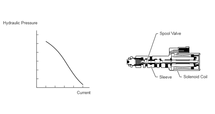
Shift solenoid velve SLT controls the transmission line pressure for smooth transmission operation based on signals from the throtte position sensor and vehicle speed sensor. The ECM adjusts the current to shift solenoid valve SLT to control the hydraulic line pressure coming from the primary regulator valve. Appropriate line pressure assures smooth shifting with varying engine output.
| DTC Code | DTC Detection Condition | Trouble Area |
|---|---|---|
| P0894 | The ECM detects a malfunction on SLT, S1, S2, S3, S4, SL2, gear 6 incorrect ratio (sequence valve) or 1-2 shift solenoid valve according to the revolution difference of the turbine and the output shaft, and also by the oil pressure. (2-trip detection logic) | ·Shift solenoid valve SLT remains open or closed·Shift solenoid valve S1, S2, S3, S4 or SL2 remains open or closed·Gear 6 incorrect ratio (sequence valve) or 1-2 shift valve is stuck·Valve body is blocked·Automatic transmission (clutch, brake, gear, etc.) |
| P2714 | The ECM detects a malfunction on SLT (ON side) according to the revolution difference of the turbine and the output shaft, and also by the oil pressure (2 trip detection logic) | ·Shift solenoid valve SLT remains open or closed·Shift solenoid valve S1, S2, S3, S4 or SL2 remains open or closed·Gear 6 incorrect ratio (sequence valve) or 1-2 shift valve is stuck·Valve body is blocked·Automatic transmission (clutch, brake, gear, etc.) |
Procedure
1. Check DTC output (in additon to DTCs P0894 and P2714)
a. connect the diagnostic scanners.
b. Turn the iginition switch to ON.
c. Read the DTCs.
| Result | Proceed to |
|---|---|
| ·Only P0894 is output·Only P0894 and P2714 are output | A |
| P0894, P2714 and other DTCs are output | B |
A>> Perform active test shift solenoid valve SLT.
B>> Go to DTC chart.
2. Perform active tst shift solenoid valve SLT.
Notice:
– Perform the test at the normal operating ATF temperature: 50 to 80°C (122 to 176°F).
– Be careful to prevent SST’s hose from interfering with the exhaust pipe.
– Perform the test with the A/C OFF.
a. Remove the test plug on the transmission case center right side and connect SST.
b. Connect the diagnostic scanners.
c. Start the engine and warm it up.d. Measure the line pressure with SST.
d. According to the display on the diagnostic, perform the actice test.
e. Measure th line pressure.
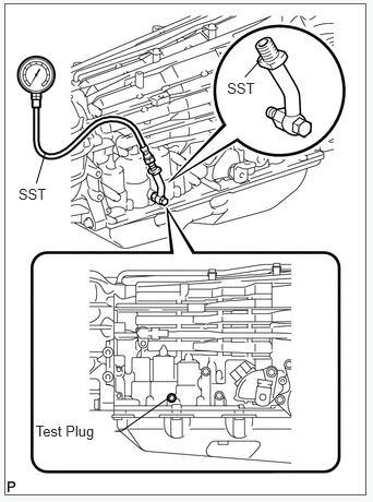
| Tester Display | Test Part | Control Range | Diagnostic Note |
|---|---|---|---|
| Activate the Solenoid (SLT)* | Operate shift solenoid SLT and raise line pressure | ON or OFF HINT:·OFF: Line pressure up (when Active Test “Activate the Solenoid (SLT)” is performed, ECM commands SLT solenoid to turn OFF)·ON: No action (normal operation) | [Vehicle Condition] ·Vehicle stopped·Engine idling |
OK: the line pressure changes as specified when performing the active test.
OK>> perform active test.
NG>> Inspect shfit solenoid valve SLT.
3. Perform active test(running test)
caution: this test should always be performed with at least 2 people.
a. Connect the diagnostic scanners.
b. Clear the DTC.
c. Warm up the engine.
d. According to the display on the diagnostic, perform the active test.
| Tester Display | Test Part | Control Range | Diagnostic Note |
|---|---|---|---|
| Control the Shift Position | Operate shift solenoid valve and set each shift position | ·Press “→” button: Shift up·Press “←” button: Shift down | Possible to check operation of shift solenoid valves [Vehicle Condition] 50 km/h (30 mph) or less |
f. Compare the ECM gear shift command and the actual gear position.
OK: Gear position changes in accordance with the diagnostic tools cmmande.
| System Condition | ECM Gear Shift Command | Proceed to | |||||||
|---|---|---|---|---|---|---|---|---|---|
| 1st | 2nd | 3rd | 4th | 5th | 6th | ||||
| Malfunction | Shift solenoid S1 | Stuck ON*1 | 2nd | 2nd | 3rd | 4th | 5th | 6th | A |
| Stuck OFF | 1st | 1st | 3rd | 4th | 5th | N*2 | |||
| Shift solenoid S2 | Stuck ON | 1st | 2nd | 2nd | 4th | 6th | 6th | B | |
| Stuck OFF | 3rd | 3rd | 3rd | 4th | 5th | 5th | |||
| Shift solenoid S3 | Stuck ON | 1st | 2nd | 3rd | 3rd | N*2 | N*2 | C | |
| Stuck OFF | 3rd | 4th | 4th | 4th | 5th | 6th | |||
| Shift solenoid S4 | Stuck ON*3 | 1st | 2nd | 3rd | 4th | 5th | 6th | D | |
| Stuck OFF | 1st | 2nd | 3rd | 4th | 4th | 4th | |||
| Normal | 1st | 2nd | 3rd | 4th | 5th | 6th | E | ||
A>> Go to step 4.
B>> Go to step 5.
C>> Go to step 6.
D>> Go to step 7.
E>> Go to step 9.
4. Inspect shift solenoid valve S1.
a. Remove shift solenoid valve S1.
Measure the resistance acoording to the value(s) in the table below.
| Tester Connection | Condition | Specified Condition |
|---|---|---|
| Shift solenoid valve S1 connector terminal – Shift solenoid valve S1 body | 20°C (68°F) | 11 to 15 Ω |
c. Connect the battery’s possitve (+) lead to terminal of the solenoid valve connector, and the negative (-) lead to the solenoid valve body. Then check that the valve moves and makes an operating noise.
OK>> valve moves and makes an operating noise.
| Result | Proceed to |
|---|---|
| NG | A |
| OK | B |
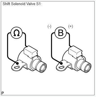
A: Replace shift solenoid valve S1.
B: Inspect transmisison valve body assembly.
5. Inspect shift solenoid valve S2.
a. remove shift solenoid valve S2.
b. Measure the resistance according to the value(s) in the table below.
| Tester Connection | Condition | Specified Condition |
|---|---|---|
| Shift solenoid valve S2 connector terminal – Shift solenoid valve S2 body | 20°C (68°F) | 11 to 15 Ω |
c. Connect the battery’s positive (+) lead to the terminal of the solenoid valve connector, and the negative (-) lead to the solenoid valve body. Then check that the valve moves and makes an operating noise.
| Result | Proceed to |
|---|---|
| NG | A |
| OK | B |
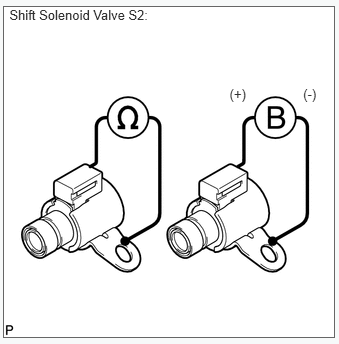
A: Repalce shift solenoid valve S2.
B: Go to step 10.
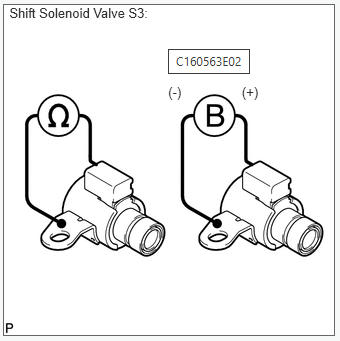
6. Inspect shift solenoid valve S3.
a. Remove shift solenoid valve S3.
b. Measure the resistance according to the value(s) in the table below.
| Tester Connection | Condition | Specified Condition |
|---|---|---|
| Shift solenoid valve S3 connector terminal – Shift solenoid valve S3 body | 20°C (68°F) | 11 to 15 Ω |
c. Connect the battery’s positive (+) lead to the terminal of the solenoid valve connector, and the negative (-) lead to the solenoid valve body. Then check that the valve moves and makes an operating noise.
| Result | Proceed to |
|---|---|
| NG | A |
| OK | B |
A:Repalce shift solenoid valve S3.
B: Go to step 10.
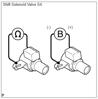
7. 6. Inspect shift solenoid valve S4.
a. Remove shift solenoid valve S4.
b. Measure the resistance according to the value(s) in the table below.
| Tester Connection | Condition | Specified Condition |
|---|---|---|
| Shift solenoid valve S4 connector terminal – Shift solenoid valve S4 body | 20°C (68°F) | 11 to 15 Ω |
c. Connect the battery’s positive (+) lead to the terminal of the solenoid valve connector, and the negative (-) lead to the solenoid valve body. Then check that the valve moves and makes an operating noise.
OK: Go to step 8.
NG: Repalce shift solenoid valve S4.
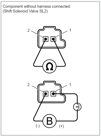
8. Inspect shift solenoid valve SL2.
a. Remove shift solenoid valve SL2.
b. Measure the resistance according to the value(s) in the table below.
| Tester Connection | Condition | Specified Condition |
|---|---|---|
| 1 – 2 | 20°C (68°F) | 5.0 to 5.6 Ω |
c. Connect the battery’s positive (+) lead with a 21 W bulb to terminal 1 and the negative (-) lead to terminal 2 of the solenoid valve connector. Then check that the valve moves and makes an operating noise.
| Result | Proceed to |
|---|---|
| NG | A |
| OK | B |
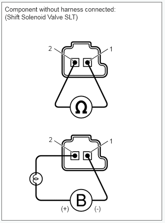
9. Inspect shift solenoid valve SLT.
a. Remove shift solenoid valve SLT
b. Measure the resistance according to the value(s) in the table below.
| Tester Connection | Condition | Specified Condition |
|---|---|---|
| 1 – 2 | 20°C (68°F) | 5.0 to 5.6 Ω |
Connect the battery’s positive (+) lead with a 21 W bulb to terminal 2 and the negative (-) lead to terminal 1 of the solenoid valve connector. Then check that the valve moves and makes an operating noise.
Ok: Inspect transmission valve body assembly.
NG: Replace shift solenoid valve SLT>
10. Inspect transmission valve body assembly.
a. Check the transmission valve body assembly.
OK: There are no foreign objects on any valve.
OK: Go to step 11.
NG: Repair or replace transmission valve bodytassembly.
11. Inspect torque converter assembly.
Check the torque converter assembly. OK: The torque converter operates normally.
OK>> Repair or replace automatic transmission assembly.
NG>> Replace torque converter assembly.