P0705 Transmission Range Sensor Circuit Malfunction (PRNDL Input)
Description:
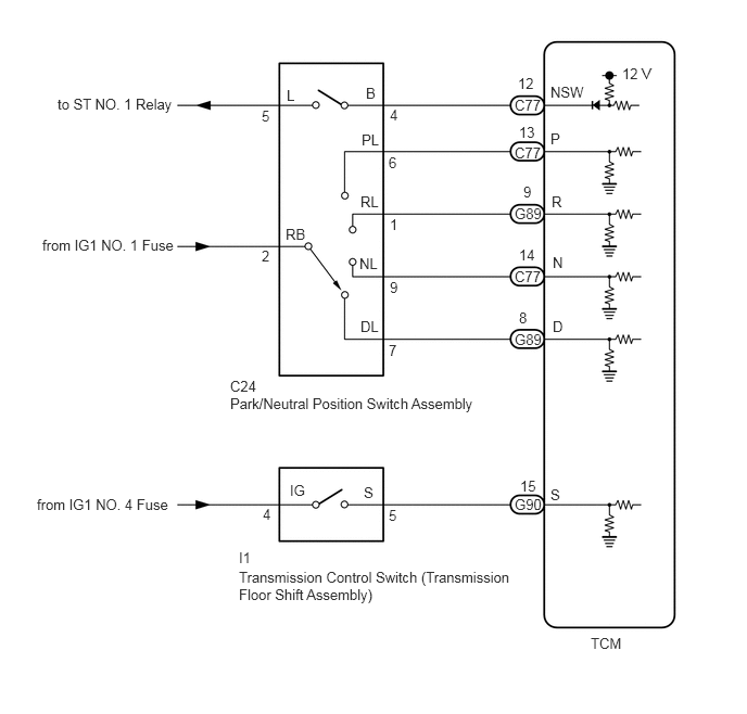
The park/neutral position switch assembly detects the shift lever position and sends signals to the TCM.
| DTC No. | Detection Item | DTC Detection Condition | Trouble Area | MIL | Memory |
|---|---|---|---|---|---|
| P0705 | Transmission Range Sensor Circuit Malfunction (PRNDL Input) | One of the following conditions is met: (A) Any 2 or more of the following signals are ON simultaneously (2-trip detection logic): ·One of the following conditions is met·P input signal is ON·N input signal is ON·NSW input signal is ON·R input signal·D input signal (B) Any of the following signals is ON for 2.0 seconds or more with the shift lever in S (2-trip detection logic): ·P input signal·N input signal·NSW input signal·R input signal (C) All signals are OFF simultaneously for NSW, P, R, N and D (2-trip detection logic). | ·Open or short in park/neutral position switch circuit·Transmission control switch (transmission floor shift assembly)·Park/neutral position switch assembly·TCM | Comes on | DTC stored |
Wiring diagram:
Procedure:
1. Check harness and connector (Battery – park/neutral position switch)
a. Disconnect the park/neutral position switch assembly connector.
b.Measure the voltage according to the value(s) in the table below.Standard Voltage:
| Tester Connection | Switch Condition | Specified Condition |
|---|---|---|
| C24-2 (RB) – Body ground | Ignition switch ON | 11 to 14 V |
| C24-2 (RB) – Body ground | Ignition switch off | Below 1 V |
Disconnect the park/neutral position switch assembly connector.
b.
Measure the voltage according to the value(s) in the table below.Standard Voltage:
| Tester Connection | Switch Condition | Specified Condition |
|---|---|---|
| C24-2 (RB) – Body ground | Ignition switch ON | 11 to 14 V |
| C24-2 (RB) – Body ground | Ignition switch off | Below 1 V |
2. Check harness and connector (NSW terminal voltage)
a. Disconnect the park/neutral position switch assembly connector.
b.Measure the voltage according to the value(s) in the table below.Standard Voltage:
| Tester Connection | Switch Condition | Specified Condition |
|---|---|---|
| C24-4 (B) – Body ground | Ignition switch ON | 11 to 14 V |
| C24-4 (B) – Body ground | Ignition switch off | Below 1 V |
Disconnect the park/neutral position switch assembly connector.
b.
Measure the voltage according to the value(s) in the table below.Standard Voltage:
| Tester Connection | Switch Condition | Specified Condition |
|---|---|---|
| C24-4 (B) – Body ground | Ignition switch ON | 11 to 14 V |
| C24-4 (B) – Body ground | Ignition switch off | Below 1 V |
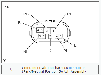
3. Inspect park/neutral position switch assembly.
Measure the resistance according to the value(s) in the table below.Standard Resistance:
| Tester Connection | Condition | Specified Condition |
|---|---|---|
| 4 (B) – 5 (L) | Shift lever in P or N | Below 1 Ω |
| 2 (RB) – 6 (PL) | Shift lever in P | Below 1 Ω |
| 2 (RB) – 1 (RL) | Shift lever in R | Below 1 Ω |
| 2 (RB) – 9 (NL) | Shift lever in N | Below 1 Ω |
| 2 (RB) – 7 (DL) | Shift lever in D, S, “+” or “-“ | Below 1 Ω |
| 4 (B) – 5 (L) | Shift lever not in P or N | 10 kΩ or higher |
| 2 (RB) – 6 (PL) | Shift lever not in P | 10 kΩ or higher |
| 2 (RB) – 1 (RL) | Shift lever not in R | 10 kΩ or higher |
| 2 (RB) – 9 (NL) | Shift lever not in N | 10 kΩ or higher |
| 2 (RB) – 7 (DL) | Shift lever not in D, S, “+” or “-“ | 10 kΩ or higher |
4. Check harness and connector (battery – transmission control switch)
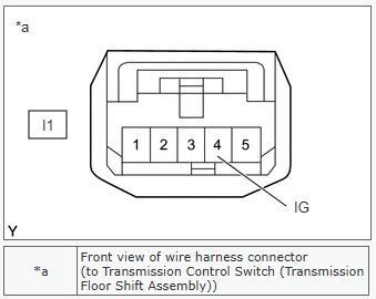
Measure the voltage according to the value(s) in the table below.Standard Voltage:
| Tester Connection | Switch Condition | Specified Condition |
|---|---|---|
| I1-4 (IG) – Body ground | Ignition switch ON | 11 to 14 V |
| I1-4 (IG) – Body ground | Ignition switch off | Below 1 V |
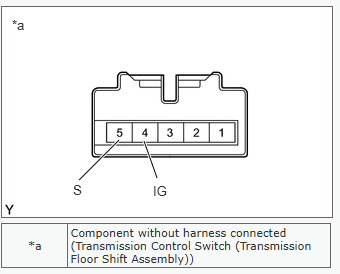
5. Inspection transmission control switch (Transmission floor shift assembly)
Measure the resistance according to the value(s) in the table below.Standard Resistance:
| Tester Connection | Condition | Specified Condition |
|---|---|---|
| 4 (IG) – 5 (S) | Shift lever in S, “+” or “-“ | Below 1 Ω |
| 4 (IG) – 5 (S) | Shift lever not in S, “+” or “-“ | 10 kΩ or higher |
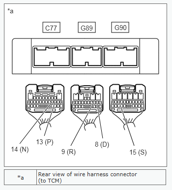
6. Check Harness and connector (park/neutral position switch, tramsmission control switch -TCM)
Measure the voltage according to the value(s) in the table below.Standard Voltage:
| Tester Connection | Condition | Specified Condition |
|---|---|---|
| C77-13 (P) – Body ground | ·Ignition switch ON·Shift lever in P | 11 to 14 V |
| G89-9 (R) – Body ground | ·Ignition switch ON·Shift lever in R | 11 to 14 V* |
| C77-14 (N) – Body ground | ·Ignition switch ON·Shift lever in N | 11 to 14 V |
| G89-8 (D) – Body ground | ·Ignition switch ON·Shift lever in D, S, “+” or “-“ | 11 to 14 V |
| G90-15 (S) – Body ground | ·Ignition switch ON·Shift lever in S, “+” or “-“ | 11 to 14 V |
| C77-13 (P) – Body ground | ·Ignition switch ON·Shift lever not in P | Below 1 V |
| G89-9 (R) – Body ground | ·Ignition switch ON·Shift lever not in R | Below 1 V |
| C77-14 (N) – Body ground | ·Ignition switch ON·Shift lever not in N | Below 1 V |
| G89-8 (D) – Body ground | ·Ignition switch ON·Shift lever not in D, S, “+” or “-“ | Below 1 V |
| G90-15 (S) – Body ground | ·Ignition switch ON·Shift lever not in S, “+” or “-“ | Below 1 V |