P0724 Brake Switch “B” Circuit High
Description:
The purpose of this circuit is to prevent the engine from stalling while driving in the lock-up condition when the brakes are suddenly applied.
When the brake pedal is depressed, this switch sends signal to the ECM. Then the ECM cancels the operation of the lock-up clutch while braking is in progress.
| DTC Code | DTC Detection Condition | Trouble Area |
|---|---|---|
| P0724 | The stop light switch remains ON even when the vehicle is driven in a STOP (less than 3 km/h (1.86 mph)) and GO (30 km/h (18.65 mph) or more) pattern 5 times. (2-trip detection logic) | ·Short in stop light switch signal circuit·Stop light switch·ECM |
Typical enabling coditions:
The stop light switch remains ON during GO to STOP 5 times.
| The monitor will run whenever the following DTCs are not stored | None |
| Battery voltage | 8 V or higher |
| Ignition switch | ON |
| Starter | OFF |
| GO: (Vehicle speed is 30 km/h (18.65 mph) or more) | Once |
| STOP: (Vehicle speed is less than 3 km/h (1.86 mph)) | Once |
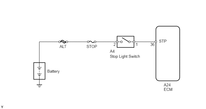
Wiring diagram:
Datalist:
| Tester Display | Measurement Item/Range | Normal Condition | Diagnostic Note |
|---|---|---|---|
| Stop Light Switch | Stop light switch status/ ON or OFF | Brake pedal is: ·Depressed: ON·Released: OFF | – |
Procedure:
1. Inspect stop light switch.
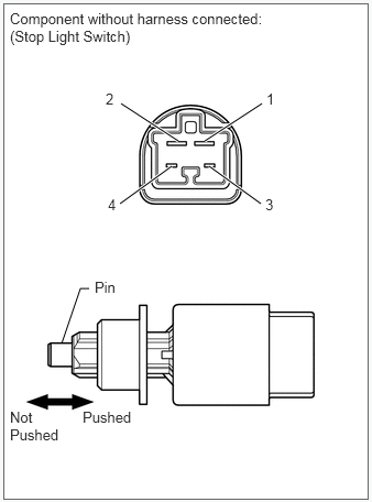
a. Remove the stop light switch.
b. Measure the resistance according to the valvue(S) in the table below.
| Tester Connection | Switch Condition | Specified Condition |
|---|---|---|
| 1 – 2 | Pin not pushed | Below 1 Ω |
| 3 – 4 | Pin pushed | Below 1 Ω |
| 1 – 2 | Pin pushed | 10 kΩ or higher |
| 3 – 4 | Pin not pushed | 10 kΩ or higher |
2. Check harness and connector (Battery – ECM).
a. Disconnect the A24 ECM connector.
b. Measure the voltage according to the value(s) in the table below.
| Tester Connection | Condition | Specified Condition |
|---|---|---|
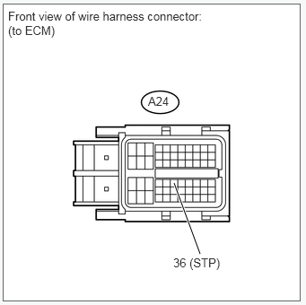
| A24-36 (STP) – Body ground | Brake pedal is depressed | 11 to 14 V |
| A24-36 (STP) – Body ground | Brake pedal is released | Below 1 V |
| Result | Proceed to |
|---|---|
| NG | A |
| OK | B |
NG >> Repair or replace harness or connector.
OK >> Replace ECM.