P0500 – Vehicle Speed Sensor Malfuntion (A750F)
Description:
The speed sensor detects the wheel speed and sends the appropriate signals to the skid control ECU. The skid control ECU converts these wheel speed signals into a pulse signal and outputs it to the TCM via the combination meter. The TCM determines the vehicle speed based on the frequency of this pulse signal.
| DTC No. | Detection Item | DTC Detection Condition | Trouble Area | MIL | Memory |
|---|---|---|---|---|---|
| P0500 | Vehicle Speed Sensor Malfunction | While the vehicle is being driven at 9 km/h (5.59 mph) or more, no vehicle speed sensor signal is transmitted to the TCM for 5 seconds or more (2-trip detection logic). | ·Open or short in speed signal SPD1 circuit·Combination meter system·TCM | Comes on | DTC stored |
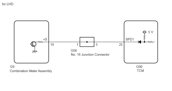
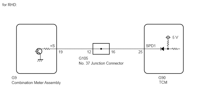
Wiring diagram:
Procedure:
1. Read the value displayed on the GTS.Powertrain > ECT > Data List
| Tester Display | Measurement Item | Range | Normal Condition | Diagnostic Note |
|---|---|---|---|---|
| Vehicle Speed | Vehicle speed | Min.: 0 km/h (0 mph) Max.: 255 km/h (158 mph) | Actual vehicle speed | – |
2. CHECK COMBINATION METER SYSTEM
3. CHECK HARNESS AND CONNECTOR (COMBINATION METER ASSEMBLY – TCM)
Measure the resistance according to the value(s) in the table below.Standard Resistance:
| Tester Connection | Condition | Specified Condition |
|---|---|---|
| G9-19 (+S) – G90-25 (SPD1) | Always | Below 1 Ω |
4.CHECK HARNESS AND CONNECTOR (JUNCTION CONNECTOR – TCM)
Measure the resistance according to the value(s) in the table below.Standard Resistance:
| Tester Connection | Condition | Specified Condition |
|---|---|---|
| G56-5 – G90-25 (SPD1) | Always | Below 1 Ω |
| Tester Connection | Condition | Specified Condition |
|---|---|---|
| G105-16 – G90-25 (SPD1) | Always | Below 1 Ω |